
At Central Patternmaking we work closely with a number of UK Polyurethane processors, producing tooling for a wide spectrum of components including automotive, aerospace, electronics, defence, point of sale and many more. Although we have gained a great deal of knowledge about the processing of different types and grades of materials, we will always be reliant on the expertise of our partners to advise on how best to incorporate specific requirements into the design of the mould tool to suit their production methods.
We have listed 10 critical points to cover during the design stage to ensure that we supply a mould tool that performs to the processor's requirements.
What component information is required?
The majority of mould tools are designed and manufactured directly from customer-supplied CAD models of the components. Alternatively, the CAD models can be created from 2D drawings or by scanning existing components.
What base material is to be used for the tooling?
Our partners will generally specify what material they require the mould tool to be manufactured from. This will mainly depend on the volume of parts required, timescale and budget.
Small lifespan production or prototype tooling can be manufactured from resin or tooling board, with the advantage of reducing the cost and lead time of the mould. However, there are limitations, such as increased wear of the mould faces, and other disadvantages that we'll touch upon later in this blog.
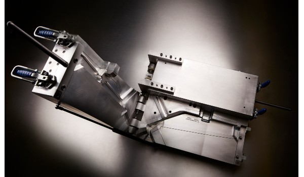
Larger production requirements and long lifespan components tend to be manufactured from aluminium billets or cast aluminium, increasing the life of the tool. There are also other major advantages to using aluminium that we'll cover, including temperature control and surface finish.
How will the tooling be mounted and used during production?
The design stage starts by establishing how the mould is to be used in production. There are a number of tooling configurations to consider, from the tool being mounted on a multi-stage carousel to a simple hand-operated lift between the 2 parts of the mould. The design could also incorporate gas struts and hinged opening to aid operator use, or tooling can be mounted separately on a mobile stand, press mounted, and so on.
How many parts to be produced from each cycle?
Depending on the production volumes, our partners will generally advise on the number of parts required per cycle, and therefore how many cavities required per mould tool. There are obvious constraints regarding the dimensions of the components, the size of the tooling and the process time to fill each cavity. These will be discussed during this stage in order to confirm the optimum number.
How is the temperature of the mould tool controlled during production?
Temperature control of the mould is critical in reducing cycle time, helping with the flow of material through the mould and controlling the shrinkage. To achieve a consistent temperature, heated water is pumped through a series of water channels in the mould at a set temperature. Aluminium moulds are ideally suited with a distinct advantage over resin/tooling board moulds due to the thermal conductivity of the material.
What feed system is to be used to allow material to flow into cavities?
Depending on the application, material and component geometry, various feed systems can be used to ensure a full fill of the component. From open pour to a more sophisticated gating system, the processor will advise their preferred option and how this is to be incorporated into the initial design.
What shrinkage is to be used?
Different materials and grades of materials will have different shrinkage rates once processed and cured. Although material suppliers will offer guidance on the shrinkage rate of each grade, the geometry of the component and the mould tool design can have an impact on the rate that different areas react. In conjunction with the design team, the processor may request that critical areas of the mould be manufactured with a "metal on" state or added after an initial sample trial. This will allow the parts from the initial trial to be measured, establishing the exact shrinkage, and then critical areas of the mould to be finished machined or added.
What surface finish is required?
The component may require a specific surface finish which needs to be applied to the mould. Polished and specific etched finishes can be achieved using an aluminium mould, but resin and tooling board have limited options. The design of the mould must take into account how the component will be removed from the mould without damaging the surface. If a deep grain is required, e.g. a leather pattern, it may be necessary to add draft angles to the geometry of the component.
What customer specific standards will be included in design?
The finished component may include certain features that will require the tool design to incorporate separate inserts, cores or over moulded parts. Many of our customers will specify how these will be included in the design to suit production methods. If the component geometry does not allow the part to be removed from the mould "in line of draw", the design will probably require loose cores and inserts to be either mechanically or manually repositioned to allow removal of part.
Once the design is complete, it can be reviewed by all parties prior to manufacture to ensure that the mould tool has all the features required for optimum performance.
In Summary
Ultimately, the design of the bespoke tooling is very much guided by the processor and how they need the tool to perform for their production. Therefore it's the tooling manufacturer's responsibility to fully understand the customer's requirement and work in partnership to ensure the design specification is met and, sometimes, surpassed.
If you'd like some help with reducing the cost of your next project, we’d love to hear from you. Let us know you'd like to talk by requesting a call back.
For more content like this, follow us on LinkedIn by clicking the button below.